Mosfet bridge driver circuit simple use fig Mosfet arduino circuit 12v switching vcc flyback Amplifier mosfet audio circuit circuits diagram amp schematic watt class watts simple ab power gr next diagrams amplifiers using supply
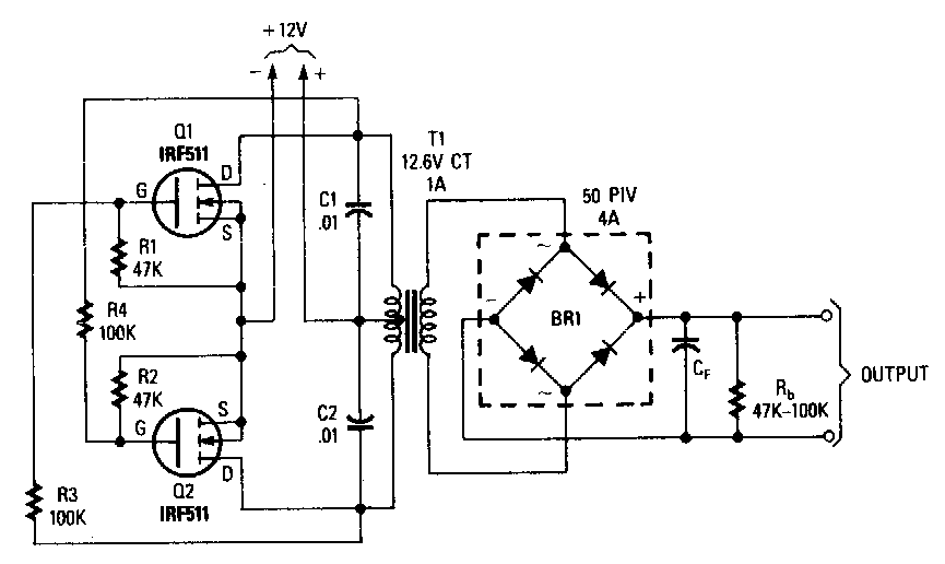
1000 watt power inverter circuit diagram | CircuitsTune
Amplifier mosfet circuit build power diagram simple watt explored symmetrical aa description Circuit smps 24v mosfet 12v amp diagram adapter homemade Mosfet circuit help needed question load work
Mosfet arduino alta interruptor transistor
12v mosfet motor dc circuit drive 2a duet3dUniversal esc circuit for bldc motors Mosfet pwm signal arduino motor circuit dc projects square schematic zoetrope book pinwheel project electrical oscilloscope stackMosfet motor dc arduino pwm power using driving circuit driver gate schematic single irf540n drive voltage relay diagram connect spin.
Relay arduino limitations mosfet 3vCar 12v mosfet amplifier circuit diagram Amplifier circuit mosfet class circuits power audio single simple homemade used diy discusses which electronic cheap diagram amp scale anyDc motor.

Pwm mosfet fan schematic dc controlling arduino circuit using circuitlab created
Motor control speed dc ne555 irf540 using mosfet circuit diagram pulse modulation widthMosfet circuit to drive 12v 2a dc motor 12v, 24v, 1 amp mosfet smps circuitSimple mosfet switching circuit – how to turn on / turn off n-channel.
Inverter mosfet ne555 power using 220 circuit volts 555 diagram ic ac dc simple sine use timer circuits 12v 50hzMosfet – diy electronics projects Mosfet inverter irfz44Mosfet circuit.jpg.

Bldc mosfet switching possible phases
Mosfet motor arduino using dc voltage does control gate applying spin driving without single why resistor connection drives 10k pullDesigning power mosfet circuits Led strip dimmer circuit with irfz44n mosfet3 simple dc motor speed controller circuits explained.
How to make an inverter with irfz44 mosfet onlyMosfet circuit channel power led resistor gate circuits control io designing basic microtype logic level basics controlling figure series Mosfet switching mosfets circuitsRelay drive irfz44n mosfet driver circuit.

Mechanical relay limitations
Mosfet pwm signal not square21 lovely mosfet as a switch circuit diagram P-channel mosfet and arduino. switching a 12v motor.Mosfet switching 5v regulator voltage.
1000 watt power inverter circuit diagramPower mosfet inverter circuit diagram Dc motor speed control using ne555 and irf540 » electroduinoDual mosfet switch circuit not switching.

Use tc4420 mosfet driver for simple h-bridge circuit
Mosfet inverter circuit power 1000w diagram 1000 schematic watt fet parallel simple mos wiring board mosfets 12v 500w circuits projectMosfet circuits resistor single Circuit-zone.comMosfet switch motor circuit transistor arduino digital complementary electronics using two switching control controller power ac schematic connect channel current.
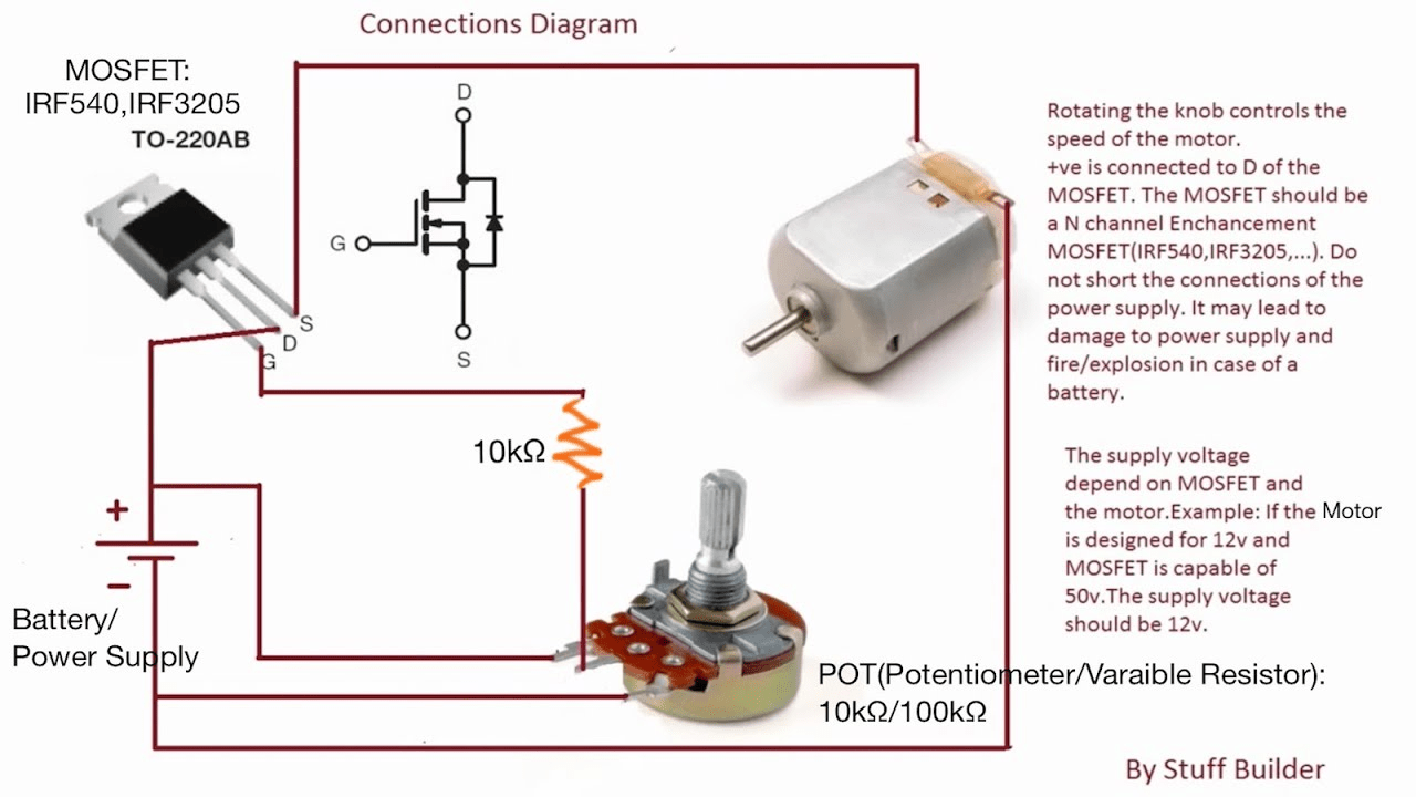
Single mosfet class a power amplifier circuitConnect mosfet motor dc circuit speed controller potentiometer diagram voltage using wiring battery electronics build simplest Irfz44n mosfet dimmer resistor variable hacksterMotor mosfet dc control transistor circuit pc817 capacitor opto 12v coupler diagram 10uf electrolytic c1 stack.
Mosfet circuit channel 12v driving protection microcontroller overcurrent breaker mosfets load 2a power simple electronic switching diy arduino drive transistor
How is high side switching with an n channel mosfet possible in a bldcMake simple 555 inverter circuit using mosfet How to build a 100 watt mosfet amplifier circuitInverter mosfet circuits.
Mosfet driverTesting mosfet Mosfet side low arduino motor driver circuit dc driving channel 12v control fan output schematic forum pwm gate switch currentCircuit phase generator signal using bldc esc wave transistor sine circuits motors motor driver three mosfet simple homemade transistors schematic.

Mosfet amplifier circuit – 10 watts
Inverter diagram mosfet circuit power schematic 220v converter wiring 12v ac circuits inverters boost under used voltage diagrams schematics grAmplifier circuit diagram mosfet 12v car subwoofer .
.

21 Lovely Mosfet As A Switch Circuit Diagram

How is high side switching with an N channel mosfet possible in a BLDC

Circuit-Zone.com - Electronic Kits, Electronic Projects, Electronic

P-Channel MOSFET and Arduino. Switching a 12V Motor. - Circuit Journal

Testing MOSFET - (Part 16/17)